

Background
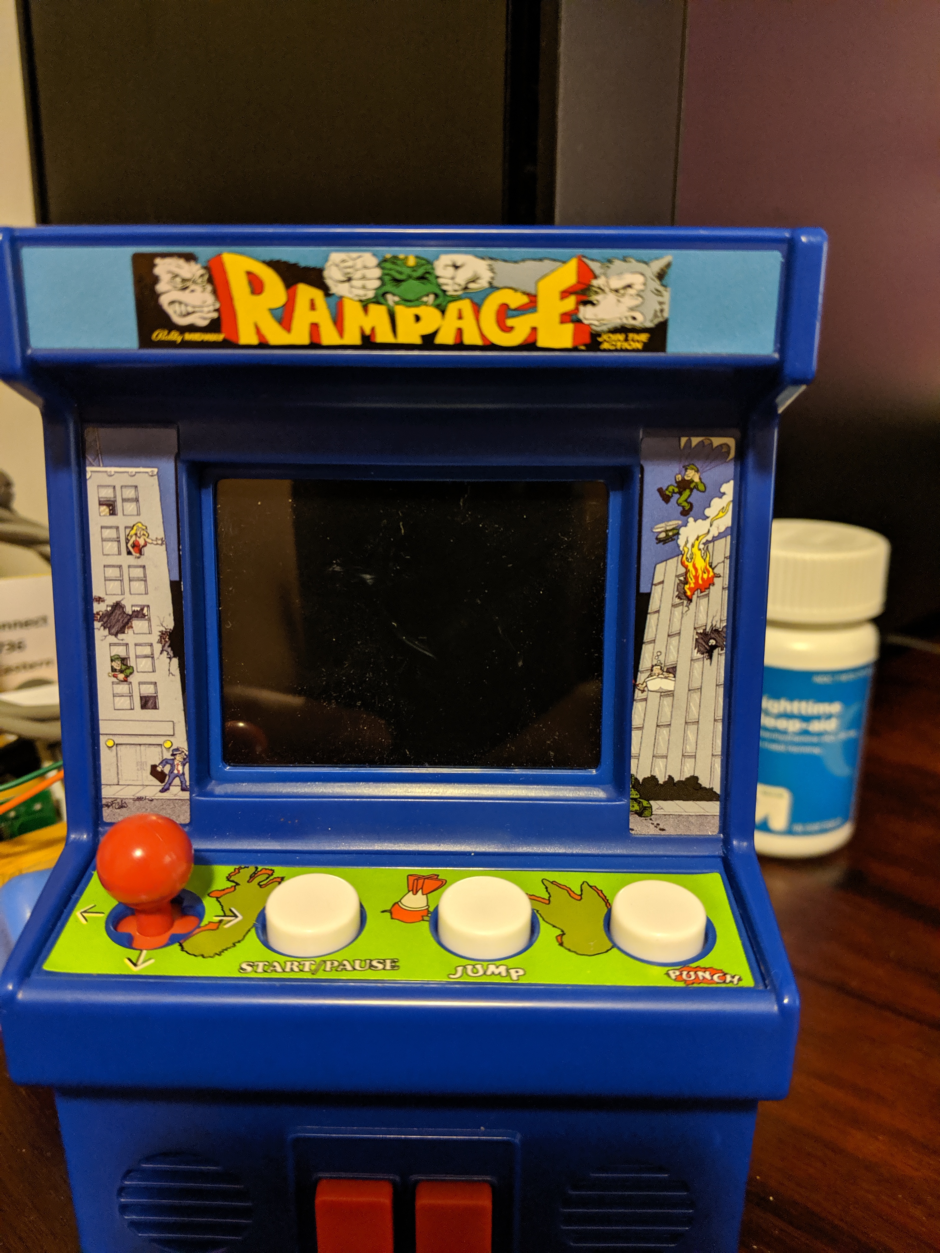
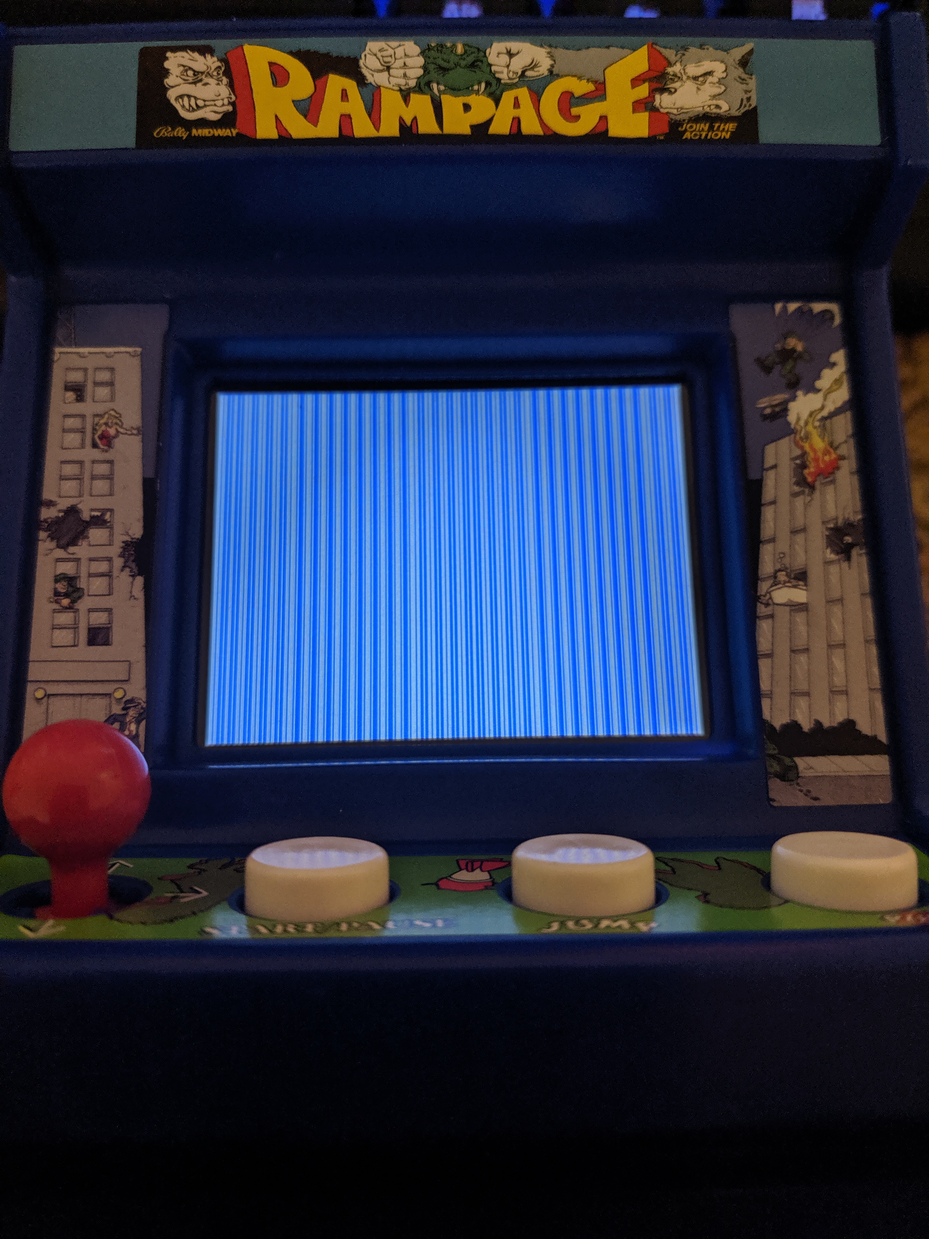
In the last post, we extracted the SPI flash, and found what appears to be a slightly modified Rampage ROM for the NES, see the differences in the start menu below:
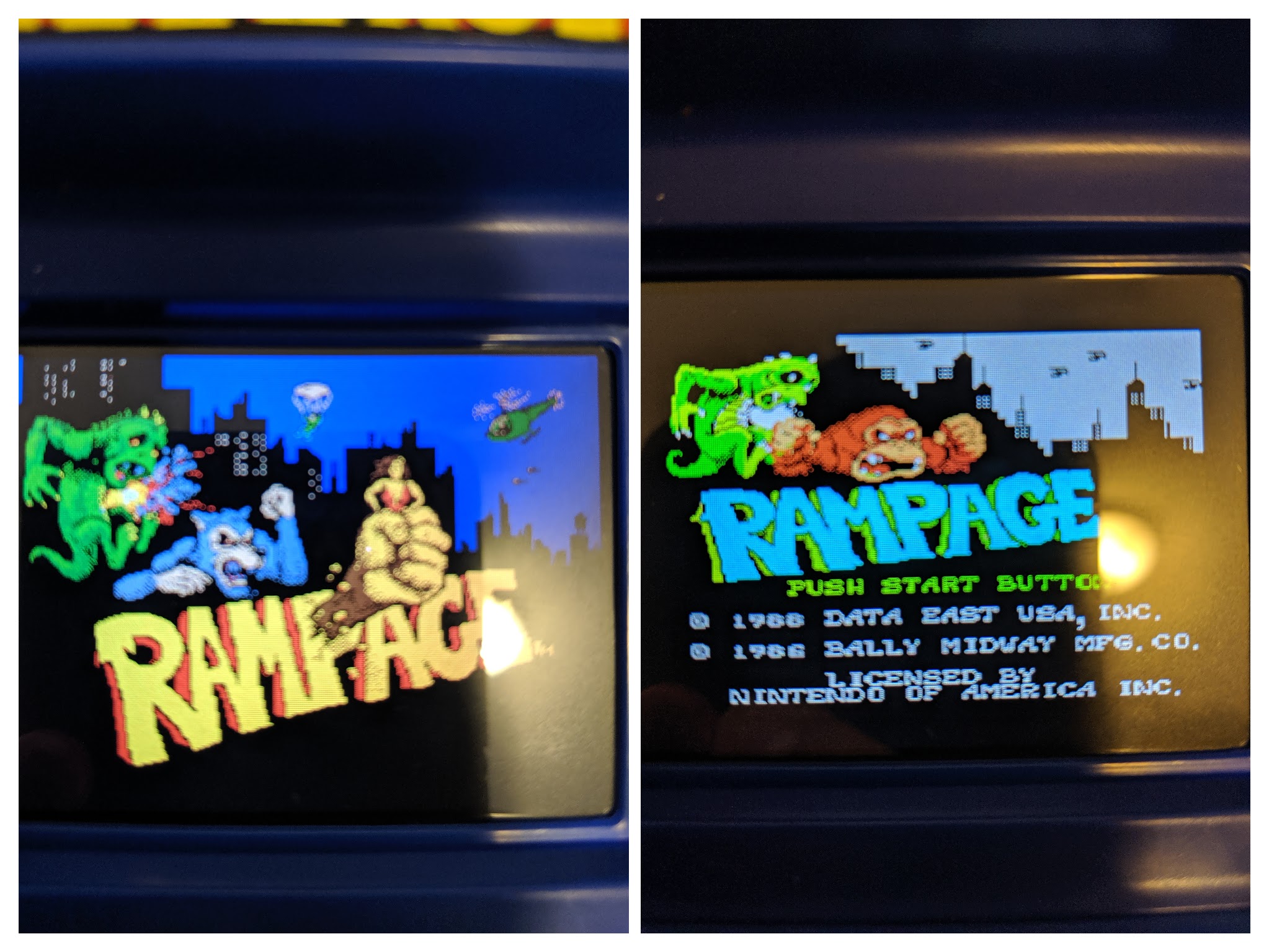
However, the gameplay looks almost identical.
Given this information I had two questions
- Can we run this version of the Rampage ROM in a NES emulator?
- Can the original ROM run on the cabinet hardware?
Before we do any of this, we need to get a better understanding of the layout of the image that we extracted.
Understanding the Flash Layout
We saw before in the previous post that the first 30k appears to be a rough copy of the NES version, with a handful of differences patched in/out
- Two player mode is nop’ed out in the binary
- The CHR tables are slightly modified as is the copyright string on the start screen
This appears to take up the first 0x30000 bytes of the SPI flash, but there is much more data than that contained in the dump we pulled, there is about 0x80000 bytes total!
What else could be in this flash image?
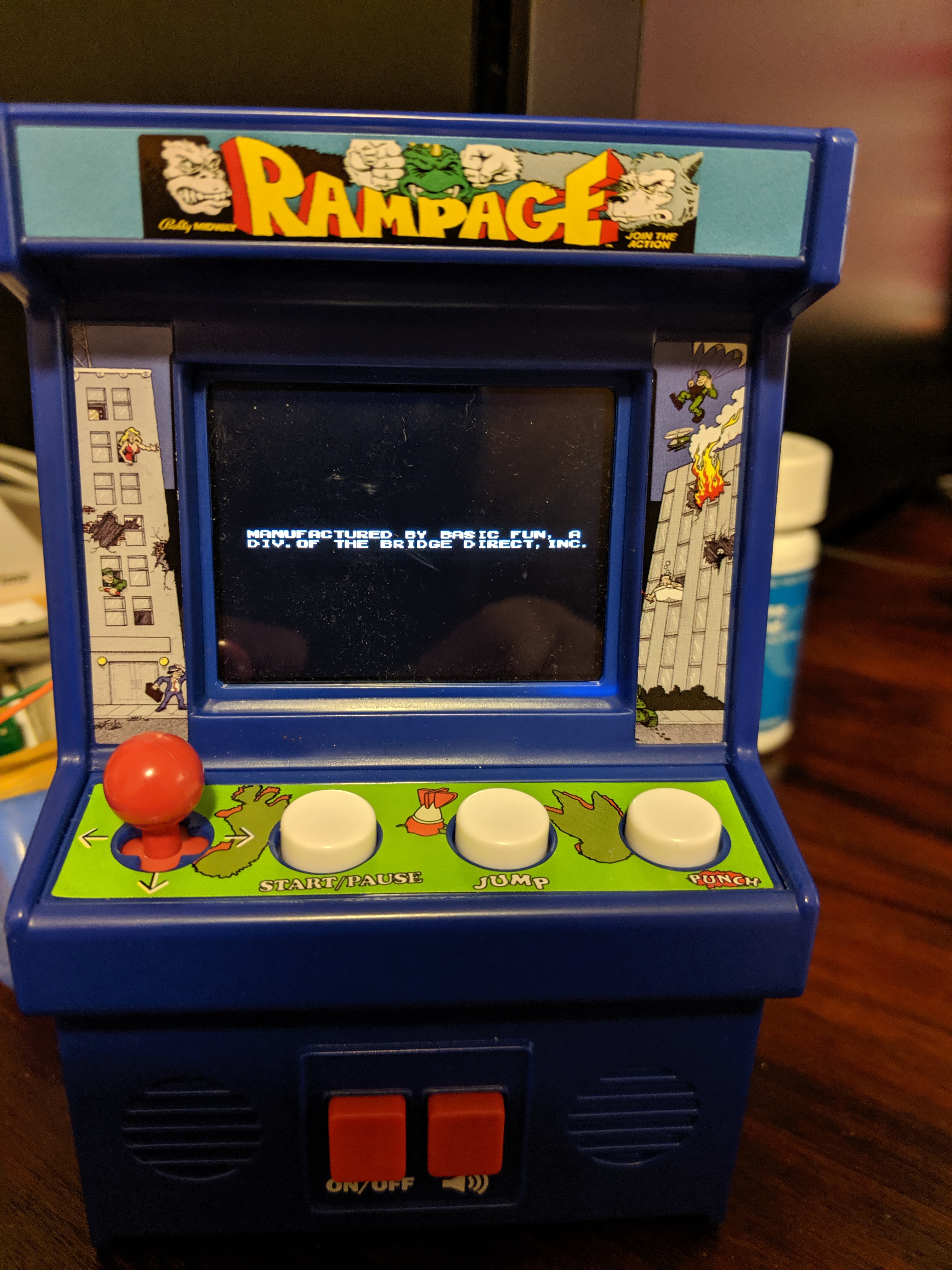
Well for starters, the startup screen that can be seen below is not a part of the original NES ROM so that is most certainly taking up some space:
And there is a test menu that can be entered by holding Start and Up on the cabinet while it is powering up, so that must be taking up some space as well!
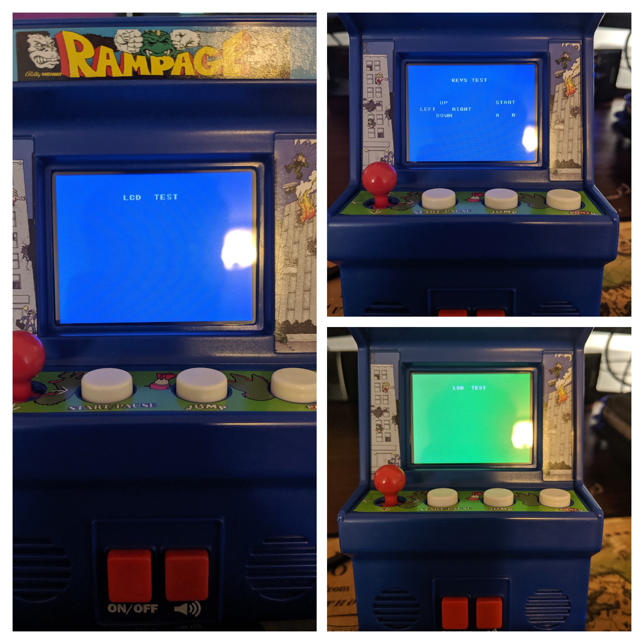
So there is likely some initial bootstrap code that is run that determines whether to jump into the debug menu or just go straight to the Rampage rom.
Moving forward let’s assume the ROM is broken up into these parts:
| Name | Offset |
|---|---|
| Game ROM (Rampage) | 0:0x30000 |
| Bootstrap Code | ??? |
| Test Menu | ??? |
Ok so now that we’ve identified how we think the flash might be laid out, what can we look for or modify to test our assumptions? Well to understand this a little better we’ll need to take a look into how NES ROMs were structured!
NES ROM Structure Crash Course
- Disclaimer A lot of this data was pulled from NESDoc which is a phenomenal resource for anyone interested in the NES’s internals!
NES ROMs contain two types of data for the most part:
- CHR-ROM: This is used to store sprites, tiles and background data, this data is processed by the Picture Processing Unit (PPU)
- PRG-ROM: This is executable code that makes up the game logic, this data is processed and accessed by the MOS6502 (CPU)
The CHR-ROM was addressable cia the PPU and the PRG-ROM was by the CPU. In order to change what data was displayed on your screen, the CPU would write to memory mapped registers that it shared with the PPU. This allowed the game logic to control what was being displayed on screen and for the CPU to read and write PPU memory.
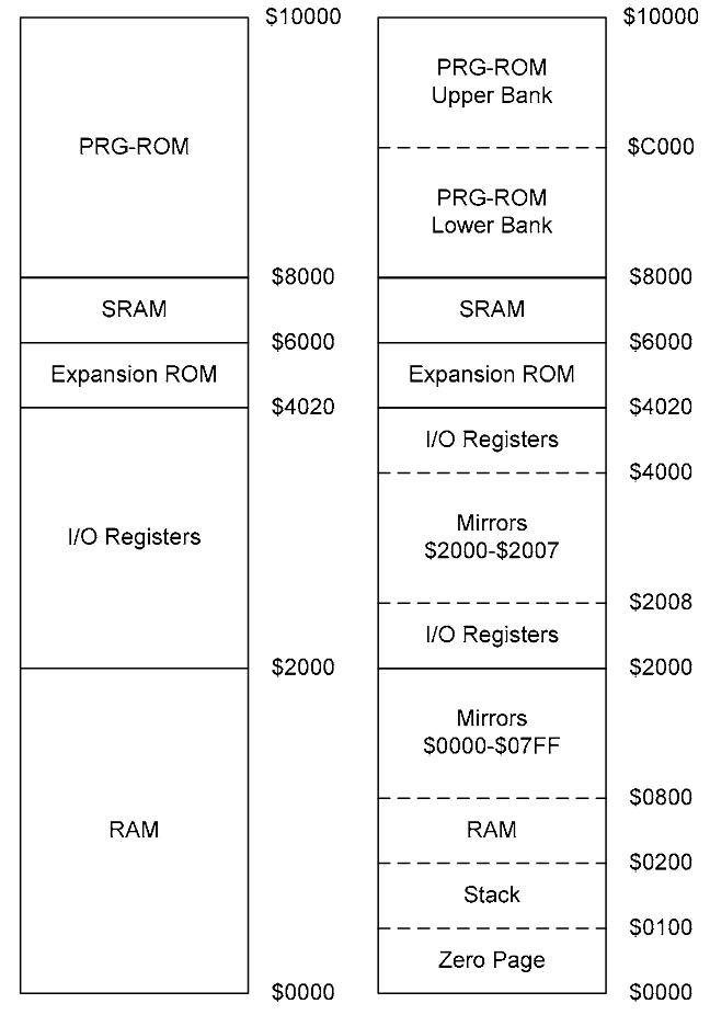
Note that the MOS6502 could address up 60 0xFFFF (16 bits of data). Two 16KB banks of that were used for storing the PRG-ROM (The game’s code), at 0x8000 and 0xC000, see the memory map below pulled from the infamous NESDoc:
The PPU only had 16K available for CHR-ROM data, and this can be seen below:
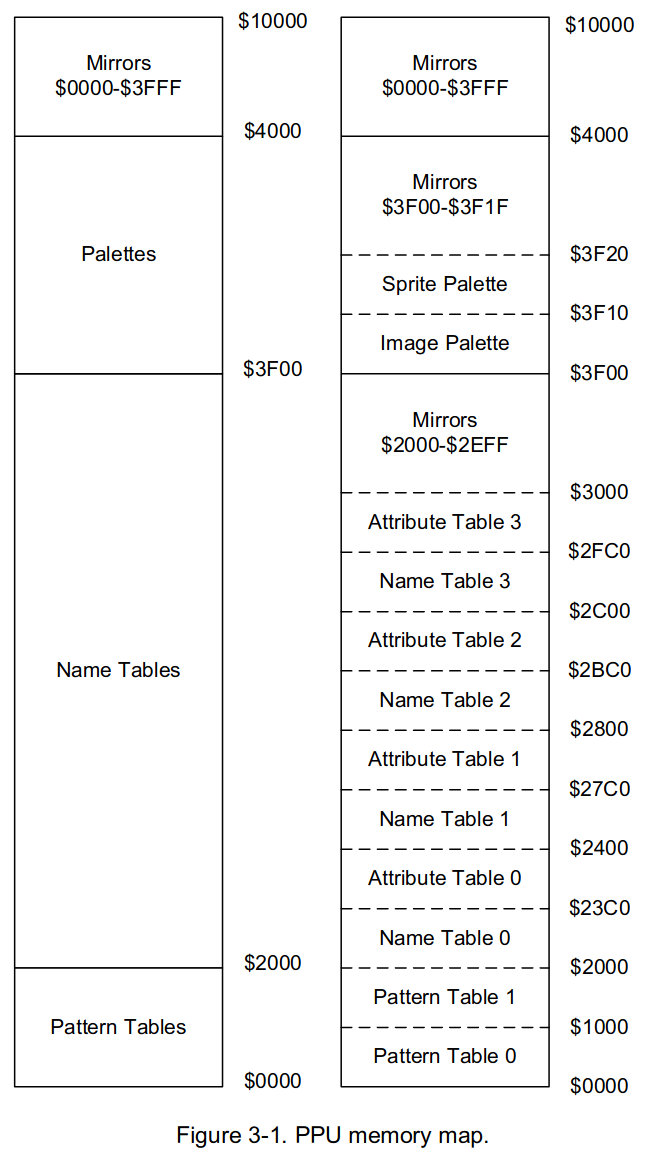
CHR-ROM would typically consist of the following structures:
- Pattern Tables: The NES can utilize two pattern tables, these store and define the 8x8 pixel tiles that can be drawn on the screen
- Name Tables: These are tables of data that select which patterns of pixel tiles are displayed whe drawing backgrounds.
- These contain 30 rows of 32 tiles each (0x3C0 bytes)
Attribute Tables: Contain information about which color pallete a given tile will use.
- Q: These PRG-ROMs and CHR-ROMs are much larger than 32kb/16kb respectively, how were they utilized?
- A: The NES used a technique known as Bank Switching to select diffent segments of ROM data.
Bank Switching Quick and Simple
Essentialy, if a game wanted to map a different section of it’s ROM (CHRor PRG) to be available to the NES, it would issue a command to a mapper this was a memory mapped hardware device on the cartridge that served as an address translator for the NES. Changing these mapper values would alter what section of the PRG-ROM and CHR-ROM was being accessed by the NES. So for example, if you had three 16kb program banks total on your cartridge, you can only access two of those at a time given the hardware within the NES. In order to access this third bank, you would issue a command to the mapper, which would essentially swap out one PRG-ROM bank for the unused one. How this was implemented in software was entirely up to the developers - they used mappers as a way to increase the available program memory on the NES!
This image is an example of how different memory banks might be used, pulled from the wikipedia article linked below

Check out the Wikipedia explanation for a more generalized example!
Bootup Assumptions
Right now I’m assuming that there is an initial loader with it’s own PRG/CHR ROM that displays the startup screen and handles the debug menu as well as prepares and launches the Rampage ROM. One thing that we can test to make sure that this is not one large contiguous ROM is replace RAMPAGE on the Flash with a ROM that uses the same mapper and is the same size, like say … Yoshi’s Cookie. I of course legally acquired a copy of this ROM from a cart that I had lying around and replaced the data at 0:0x30000 with the ROM and this was the result!
1
2
3
4
5
6
7
8
9
wrongbaud@wubuntu:~/blog/cab-work/roms$ dd if=Yoshi\'s\ Cookie\ \(USA\).nes bs=1 skip=16 of=YOSH.bin
196608+0 records in
196608+0 records out
196608 bytes (197 kB, 192 KiB) copied, 0.313231 s, 628 kB/s
wrongbaud@wubuntu:~/blog/cab-work/roms$ dd if=YOSH.bin of=../eeprom/flash.bin
384+0 records in
384+0 records out
196608 bytes (197 kB, 192 KiB) copied, 0.00276238 s, 71.2 MB/s
wrongbaud@wubuntu:~/blog/cab-work/roms$
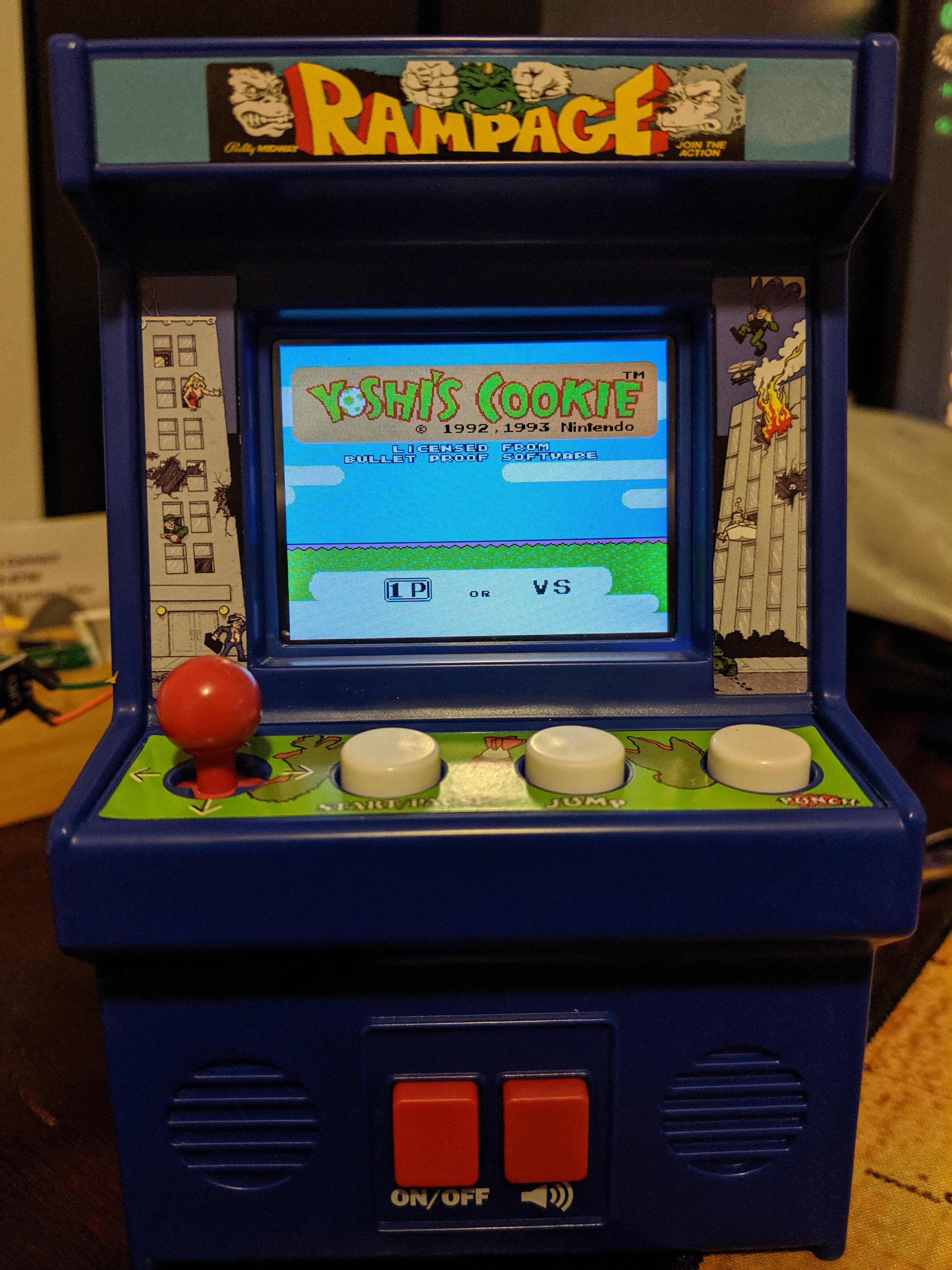
It works and is fully playable!
My hope here is that the loader configures the mapper and mirroring layout of the PPU and that we can possibly modify this in the future to run any ROMs and not just ones that share the same memory sizes and mapper chip!
Hunting for data
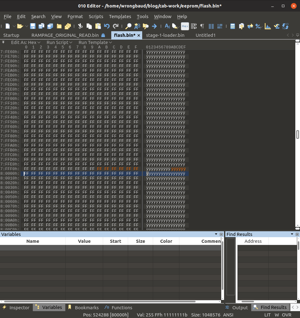
So we know that the first 0x30000 bytes of data make up the Rampage ROM, so we can ignore them from the start. There is data in the flash dump from 0x30000 to 0x80000 if we jump to 0x80000 we see an interesting set of bytes at the end that give us a hint:
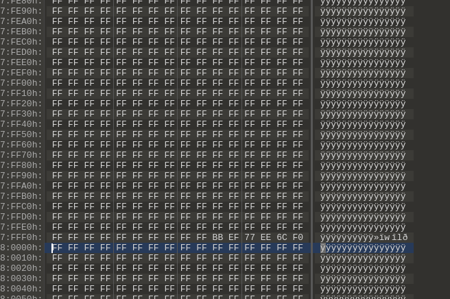
These 6 bytes at the end at 0x7FFFA:0x7FFFF likely contain the reset vector. Now you’re probably wondering “What on earth makes you say that?” – well if we look at what surrounds them we see nothing but nulls (0xFF) and we know from reading the NESDoc that reset These offsets are read in by the NES on bootup to jump the initialization code. The NES has three interrupt vectors that contain addresses within the PRG ROM that the CPU jumps to when interrupts occur. We can test this idea by replacing those bytes with 0xFF and then reflashing the cabinet, the result can be seen below:
Ah and as we can see, no signs of life whatsoever. Moving forward let’s work under the assumption that 0x7C000:0x80000 is mapped at 0xC000 on boot up by the NOAC. 0x7C000 is the assumed start point because the PRG banks were 16kb at 0x8000 and 0xC000.
So far we think we know this much about the layout:
| Start Addr | End Addr | Content |
|---|---|---|
| 0 | 0x30000 | Rampage Rom |
| 0x30000 | 0x7C000 | ??? |
| 0x30000 | 0x78000 | Code/Other Data |
| 0x78000 | 0x7C000 | 0xFF’s |
| 0x7C000 | 0x7FFFF | Initial loader? |
We still don’t know where the test menu is, or where any of the CHR data is being stored.
So what happens if we remove 0x40000:0x60000:
- Startup menu remains the same
- Debug menu remains the same
- Gameplay remains the same
This may be extra data, or a partial game that was not implemented, for now we’ll ignore it since it doesn’t seem to affect the loader or the Rampage ROM.
So what happens if we remove 0x70000:0x70B00?
This is the CHR table for the opening menu and the debug menu!
Conclusion
So we now believe that we have a solid understanding of how the ROM is structured we can load up the initial loader in Ghidra and start really digging into this! But in order to do that we’re going to need a loader or at the very least a script to properly load the NES ROM! The next post in this series will focus on using GHIDRA to reverse engineer what we know about the bootstrap code and test menu! Thanks for reading!
Blog Updates (as of 2022):
Future blog posts and entries can be found here.
If you are interested in learning more about reverse engineering check out my 5 day hardware hacking course, public and private offerings are available upon request
Never want to miss an update or blog post? Check out my mailing list for a quarterly newsletter about reverse engineering embedded devices