

Router Analysis Part 1: Hardware Teardown
Overview
In previous posts, we’ve gone over how to tear down Arcade cabinets containing SPI Flash as well as how to dissect the data that was extracted from the Rom. With this next series of posts, I’d like to take the concepts we talked about on those platforms and demonstrate them on a more popular platform
With this post our goal will be to extract the firmware from the platform and locate and type of debugging if possible (UART,JTAG,etc). We will explore multiple ways of attempting to extract the filesystem and outline the steps taken for each method.
Disclaimer: I’ve done my best to not research this router on the Internet, so I apologize if this is old information for those who look at these platforms.
Teardown
Below is a picture of the PCB after removing it from the case:
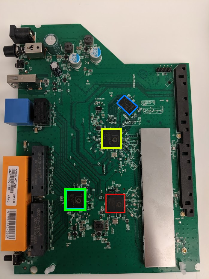
You can see the various SoCs highlighted in red/yellow/green and the SRAM highlighted in blue, otherwise this is a very straightforward board.
The CPU is highlighted in yellow, it has the part number: QCA9563-AL3A, this is going to be the main CPU that we interact with.
The chip highlighted in red has the part number QCA9880, a quick Google search returns the following wiki page
The SoC highlighted in green has the part number QCA8337N which is described in it’s data sheet as “highly integrated seven-port Gigabit Ethernet switch”
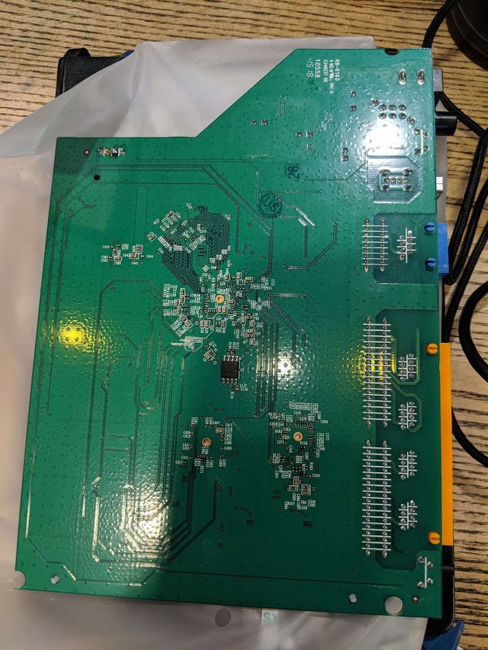
On the underside of the board there is a serial EEPROM which looks strikingly similar to those that we extracted on the Arcade cabinets in the previous posts. The EEPROM is the small black 8 pin chip in the center of the board.
Dumping the SPI flash
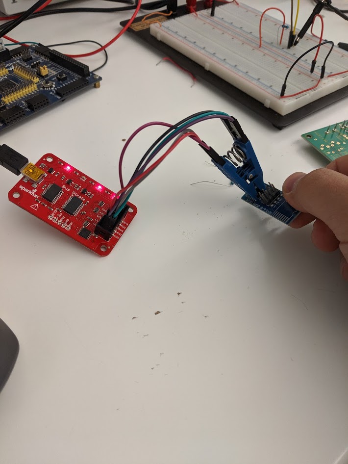
As in previous posts, this platform contains a Winbond SPI chip. Knowing what we learned about flashrom, we can hook up a buspirate and attempt get a dump of the flash. The flash chip in question is the Winbond W25Q16Fw, the data sheet can be found here
Using the pin-out from the diagram, we wire up a TSOP8 clip and connect it to the buspirate, and below are the results:
1
2
3
4
5
6
7
8
9
10
wrongbaud@wubuntu:~$ sudo flashrom -p buspirate_spi:dev=/dev/ttyUSB0 -r router.bin
[sudo] password for malt:
flashrom p1.0-131-g3a41e2a on Linux 4.15.0-64-generic (x86_64)
flashrom is free software, get the source code at https://flashrom.org

Using clock_gettime for delay loops (clk_id: 1, resolution: 1ns).
Bus Pirate firmware 6.1 and older does not support SPI speeds above 2 MHz. Limiting speed to 2 MHz.
It is recommended to upgrade to firmware 6.2 or newer.
No EEPROM/flash device found.
Note: flashrom can never write if the flash chip isn't found automatically.
It looks like we’re having some issues doing this in circuit, looking at the lines with a scope, it appears that the BusPirate can not drive the lines appropriately. After further investigation I found that the Chip Select line was not being pulled low enough, after trying a few various pull-down resistors I decided to move on from reading it in circuit. This is a common issue with trying to do any kind of in circuit reads, in order to mitigate this one can look for a reset line for the main CPU, or attempt to get the CPU into a state where it is still powering the chip but not attempting to communicate. But – since I’m a little lazy, let’s just remove it with hot air and dump it, see the pictures below and the output of binwalk on the flash image
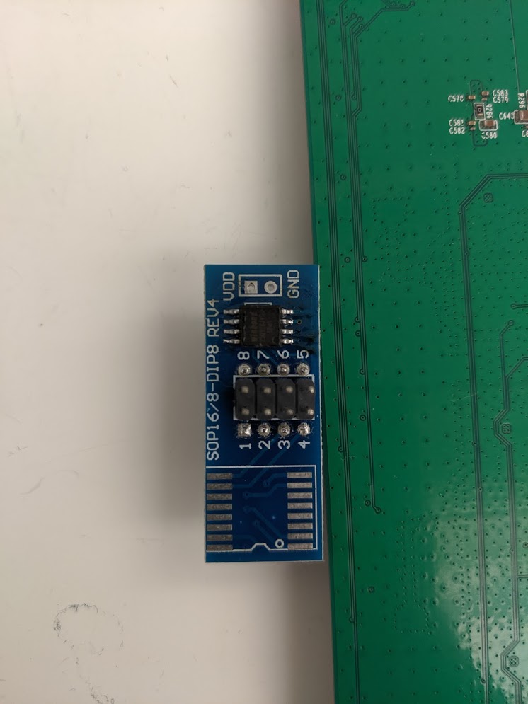
Now that we have removed the EEPROM, we see more positive results with flashrom, which is to be expected.
1
2
3
4
5
6
7
8
9
10
wrongbaud@wubuntu:~$ sudo flashrom -p buspirate_spi:dev=/dev/ttyUSB0 -r router.bin
[sudo] password for wrongbaud:
flashrom p1.0-131-g3a41e2a on Linux 4.15.0-64-generic (x86_64)
flashrom is free software, get the source code at https://flashrom.org

Using clock_gettime for delay loops (clk_id: 1, resolution: 1ns).
Bus Pirate firmware 6.1 and older does not support SPI speeds above 2 MHz. Limiting speed to 2 MHz.
It is recommended to upgrade to firmware 6.2 or newer.
Found Winbond flash chip "W25Q128.V" (16384 kB, SPI) on buspirate_spi.
Reading flash... done.
Running binwalk on the resulting image produces the following:
1
2
3
4
5
6
7
8
9
10
11
12
13
14
15
16
17
18
wrongbaud@wubuntu:~$ binwalk router.bin

DECIMAL       HEXADECIMAL     DESCRIPTION
--------------------------------------------------------------------------------
14544         0x38D0          U-Boot version string, "U-Boot 1.1.4-g14abe3ec-dirty (Aug 10 2018 - 16:06:32)"
14608         0x3910          CRC32 polynomial table, big endian
15904         0x3E20          uImage header, header size: 64 bytes, header CRC: 0x3F646F1, created: 2018-08-10 08:06:33, image size: 64400 bytes, Data Address: 0x80010000, Entry Point: 0x80010000, data CRC: 0xD54D7D12, OS: Linux, CPU: MIPS, image type: Firmware Image, compression type: lzma, image name: "u-boot image"
15968         0x3E60          LZMA compressed data, properties: 0x5D, dictionary size: 8388608 bytes, uncompressed size: 170372 bytes
144736        0x23560         U-Boot version string, "U-Boot 1.1.4-g14abe3ec-dirty (Aug 10 2018 - 16:05:04)"
144800        0x235A0         CRC32 polynomial table, big endian
146092        0x23AAC         uImage header, header size: 64 bytes, header CRC: 0x2C065C9E, created: 2018-08-10 08:05:05, image size: 40175 bytes, Data Address: 0x80010000, Entry Point: 0x80010000, data CRC: 0x5320B497, OS: Linux, CPU: MIPS, image type: Firmware Image, compression type: lzma, image name: "u-boot image"
146156        0x23AEC         LZMA compressed data, properties: 0x5D, dictionary size: 8388608 bytes, uncompressed size: 95068 bytes
262144        0x40000         uImage header, header size: 64 bytes, header CRC: 0x745A02C, created: 2018-10-26 09:44:43, image size: 1084069 bytes, Data Address: 0x80060000, Entry Point: 0x80060000, data CRC: 0x30233E01, OS: Linux, CPU: MIPS, image type: Multi-File Image, compression type: lzma, image name: "MIPS OpenWrt Linux-3.3.8"
262216        0x40048         LZMA compressed data, properties: 0x6D, dictionary size: 8388608 bytes, uncompressed size: 3155824 bytes
1441792       0x160000        Squashfs filesystem, little endian, version 4.0, compression:xz, size: 14504422 bytes, 1909 inodes, blocksize: 65536 bytes, created: 2018-12-10 02:37:18
16105480      0xF5C008        XML document, version: "1.0"
16121864      0xF60008        gzip compressed data, from Unix, last modified: 2018-12-10 07:03:02
16187400      0xF70008        gzip compressed data, maximum compression, from Unix, last modified: 2018-12-10 11:00:01
This looks promising, the SPI flash contains two U-Boot images, a Linux Kernel as well as a SquashFS filesystem, this is all fairly standard when looking at platform like this so at this point we can assume we’ve successfully dumped the flash, but as most of you probably know, these firmware images are typically obtainable online which we will discuss next.
Finding firmware online
When looking at routers such as this, it’s often very easy to find firmware online. I wanted to attempt to extract the SPI flash because that’s more in my wheelhouse being an embedded systems guy. However - the simpler path would be to go to the following link where we can find an update image! However, the ability to re-write the SPI flash can be useful in case we manage to brick the platform in the future.
Sure enough, googling the router name takes us to the following link where the firmware can be downloaded
One should note however, that these firmware images contain the root filesystem of the target and not the bootloader, which is something we would be interested in if we were to attempt to port another OS or image to this platform potentially, so there is some validation for dumping the SPI flash.
Looking For Serial
When looking at an embedded system of this class for the first time one of the first things you want to look for is a serial port, these can lead to additional debug information and in some cases even terminal access. Debug ports are often exposed via a UART and typically consist of a transmit (Tx) and receive (Rx) line.
Of course some systems only give access to Tx and other have no access at all, but it’s still a good first step to try to hunt these down when assessing an embedded system. Methods of discovery for serial terminals can vary based on the system but there are a few things that can lead to quick wins:
- Debug headers or vias
- Silk screen labeling
- Unused pads / jumpers on the PCB
So what do headers look like? What are vias? Below are some example images of what they typically look like and after looking at these you’ll notice something very similar on our board
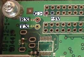
Looking at our board we can see some headers that look very similar, now we need to inspect them, but first it might help to learn a little more about what a UART actually is
UWAT? What is a UART?
UART stands for Universal Asynchronous Receiver Transmitter, this can be used for many things on an embedded system including communicating with other processors, sensor communications and of course what we’re interested in - debug access. One of the features of using a UART over something like SPI or I2C is that since it is asynchronous, there is no clock to synchronize the signals being sent between the two. In place of using a clock the transmit line utilizes start and stop bits to outline a data packet. This means that both the transmit and receive line must know the rate at which to read bits off of the wire as they come across, this is referred to as the baud rate. This is essentially the speed of the data being transferred which is typically measured in bits per second.
So if we were to look at a UART packet, we would have the following
| Location | Name | Description |
|---|---|---|
| 0:1 | Start bit | Used to signify the start of a packet |
| 1:9 | Data bits (this can also be configured to be any value really, but is commonly 8) | The data to be send / read, note that data is typically sent with the least significant bit first |
| 9:10 | Parity bit | This bit determines if data has been changed as it went over the wire |
| 10:12 | Stop bits | This signifies that the packet has ended |
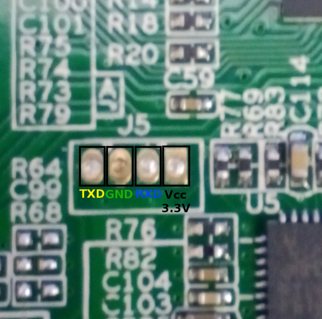
This is all great information, but in practice what does it mean for us reverse engineers? Well depending on the logic level that the UART is using, we can probe the circuit board with a multimeter and look for fluctuations in the voltage, this might lead us to a debug console that is spewing log messages, or it may just be another bus being used for sensor communications. Let’s start taking a look at the headers we outlined below and measure the voltages at each pad after the router has booted.
| Pin | Value |
|---|---|
| 1 | 3.3V |
| 2 | 0 (GND) |
| 3 | 0 |
| 4 | 3.3V |
The Tx line is typically held high in most reference designs by whoever is driving it, AKA transmitting. We have 2 possible candidates for Tx. Pins 1-3. There is a good chance that one of these is our 3.3V VCC line, we can determine that by noticing the pin’s behavior when the platform is powered down. If it is a fast drop to 0V we can assume that it is a GPIO line of some sort, if it slowly drops down to 0V, it is likely the VCC line because that slow drop is caused by capacitors that are often present on power rails! After looking at these pins on shutdown we can assume that pin 1 is VCC, as it slowly drops from 3.3V to 0V over the course of ~5 seconds. This leaves two candidates for Tx/Rx, pins 3 and 4.
Also note that we talked about how it’s often up to the transmitter to drive the line high, which would mean that the Rx line (which we would Transmit to) is likely pin 3 because it’s 0V and not connected to ground!
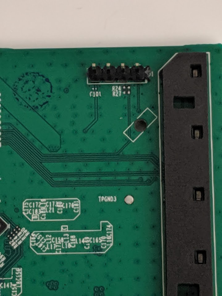
When we look at this under the scope - there is no traffic or fluctuation whatsoever. However, take a second look at the photo and notice the pads labeled R24 these pads indicate that a SMD resistor was here at some point in time and removed pre-production. Often times when looking at things like serial ports or JTAG connectors, there will be signs of resistors or other components being removed as these features are no longer needed once the device is in production. Let’s probe the left side of that pad and see what it looks like with the logic analyzer.
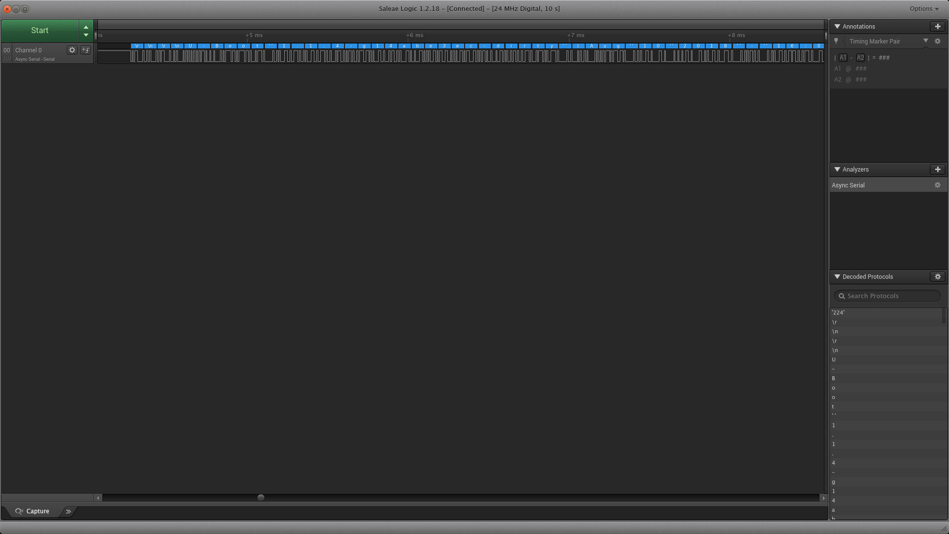
As you can see from the output of the serial analyzer, we see the string U-Boot, meaning we’ve found our Tx line. After hooking this up to an FTDI we determine that this is a serial terminal that drops us to a root shell, we could not have asked for more in this scenario. Let’s take a look at the full serial dump:
1
2
3
4
5
6
7
8
9
10
11
12
13
14
15
16
17
18
19
20
21
22
23
24
25
26
27
28
29
30
31
32
33
34
35
36
37
38
39
40
41
42
43
44
45
46
47
48
49
50
51
52
53
54
55
56
57
58
59
60
61
62
63
64
65
66
67
68
69
70
71
72
73
74
75
76
77
78
79
80
81
82
83
84
85
86
87
88
89
90
91
92
93
94
95
96
97
98
99
100
101
102
103
104
105
106
107
108
109
110
111
112
113
114
115
116
117
118
119
120
121
122
123
124
125
126
127
128
129
130
131
132
133
134
135
136
137
138
139
140
141
142
143
144
145
146
147
148
149
150
151
U-Boot 1.1.4-g14abe3ec-dirty (Aug 10 2018 - 16:05:02)

ap152 - Dragonfly 1.0

DRAM:  128 MB
Top of RAM usable for U-Boot at: 88000000
Reserving 123k for U-Boot at: 87fe0000
Reserving 16448k for malloc() at: 86fd0000
Reserving 44 Bytes for Board Info at: 86fcffd4
Reserving 36 Bytes for Global Data at: 86fcffb0
Reserving 128k for boot params() at: 86faffb0
Stack Pointer at: 86faff98
Now running in RAM - U-Boot at: 87fe0000
Flash Manuf Id 0xef, DeviceId0 0x40, DeviceId1 0x18
flash size 16MB, sector count = 256
Flash: 16 MB
Using default environment

In:    serial
Out:   serial
Err:   serial
Net:   ath_gmac_enet_initialize...
No valid address in Flash. Using fixed address
ath_gmac_enet_initialize: reset mask:c02200
athr_mgmt_init ::done
Dragonfly  ----> S17 PHY *
athrs17_reg_init: complete
SGMII in forced mode
athr_gmac_sgmii_setup SGMII done
: cfg1 0x80000000 cfg2 0x7114
eth0: 00:03:7f:09:0b:ad
eth0 up
eth0
Setting 0x181162c0 to 0x40802100
## Booting image at 9f040000 ...
   Image Name:   MIPS OpenWrt Linux-3.3.8
   Created:      2018-10-26   9:44:43 UTC
   Image Type:   MIPS Linux Multi-File Image (lzma compressed)
   Data Size:    1084069 Bytes =  1 MB
   Load Address: 80060000
   Entry Point:  80060000
   Contents:
   Image 0:  1084061 Bytes =  1 MB
   Verifying Checksum at 0x9f040040 ...OK
   Uncompressing Multi-File Image ... OK
No initrd
## Transferring control to Linux (at address 80060000) ...
## Giving linux memsize in bytes, 134217728

Starting kernel ...

[    0.000000] Linux version 3.3.8 (leo@leo-MS-7529) (gcc version 4.6.3 20120201 (prerelease) (Linaro GCC 4.6-2012.02) ) #3 Wed Oct 24 18:19:43 CST 2018
[    0.000000] bootconsole [early0] enabled
[    0.000000] CPU revision is: 00019750 (MIPS 74Kc)
[    0.000000] SoC: Qualcomm Atheros QCA956X rev 0
[    0.000000] Clocks: CPU:775.000MHz, DDR:650.000MHz, AHB:258.333MHz, Ref:25.000MHz
[    0.000000] Determined physical RAM map:
[    0.000000]  memory: 08000000 @ 00000000 (usable)
[    0.000000] User-defined physical RAM map:
[    0.000000]  memory: 08000000 @ 00000000 (usable)
[    0.000000] Initrd not found or empty - disabling initrd
[    0.000000] Zone PFN ranges:
[    0.000000]   Normal   0x00000000 -> 0x00008000
[    0.000000] Movable zone start PFN for each node
[    0.000000] Early memory PFN ranges
[    0.000000]     0: 0x00000000 -> 0x00008000
[    0.000000] Built 1 zonelists in Zone order, mobility grouping on.  Total pages: 32512
[    0.000000] Kernel command line:  console=ttyS0,115200 board=AP152 rootfstype=squashfs init=/etc/preinit mtdparts=spi0.0:128k(factory-uboot),128k(u-boot),1152k(uImage),14912k(rootfs),64k@0xff0000(ART) mem=128M rootfstype=squashfs,jffs2 noinitrd
[    0.000000] PID hash table entries: 512 (order: -1, 2048 bytes)
[    0.000000] Dentry cache hash table entries: 16384 (order: 4, 65536 bytes)
[    0.000000] Inode-cache hash table entries: 8192 (order: 3, 32768 bytes)
[    0.000000] Primary instruction cache 64kB, VIPT, 4-way, linesize 32 bytes.
[    0.000000] Primary data cache 32kB, 4-way, VIPT, cache aliases, linesize 32 bytes
[    0.000000] Writing ErrCtl register=00000000
[    0.000000] Readback ErrCtl register=00000000
[    0.000000] Memory: 126228k/131072k available (2317k kernel code, 4844k reserved, 584k data, 180k init, 0k highmem)
[    0.000000] SLUB: Genslabs=9, HWalign=32, Order=0-3, MinObjects=0, CPUs=1, Nodes=1
[    0.000000] NR_IRQS:83
[    0.000000] Calibrating delay loop... 385.84 BogoMIPS (lpj=1929216)
[    0.060000] pid_max: default: 32768 minimum: 301
[    0.060000] Mount-cache hash table entries: 512
[    0.070000] NET: Registered protocol family 16
[    0.070000] gpiochip_add: registered GPIOs 0 to 22 on device: ath79
[    0.080000] MIPS: machine is TP-LINK Archer c7 v5 support
[    0.080000] registering PCI controller with io_map_base unset
[    0.290000] bio: create slab <bio-0> at 0
[    0.300000] PCI host bridge to bus 0000:00
[    0.300000] pci_bus 0000:00: root bus resource [mem 0x12000000-0x13ffffff]
[    0.310000] pci_bus 0000:00: root bus resource [io  0x0001]
[    0.310000] pci 0000:00:00.0: BAR 0: assigned [mem 0x12000000-0x121fffff 64bit]
[    0.320000] pci 0000:00:00.0: BAR 6: assigned [mem 0x12200000-0x1220ffff pref]
[    0.320000] pci 0000:00:00.0: using irq 40 for pin 1
[    0.330000] Switching to clocksource MIPS
[    0.330000] NET: Registered protocol family 2
[    0.340000] IP route cache hash table entries: 1024 (order: 0, 4096 bytes)
[    0.340000] TCP established hash table entries: 4096 (order: 3, 32768 bytes)
[    0.350000] TCP bind hash table entries: 4096 (order: 2, 16384 bytes)
[    0.350000] TCP: Hash tables configured (established 4096 bind 4096)
[    0.360000] TCP reno registered
[    0.360000] UDP hash table entries: 256 (order: 0, 4096 bytes)
[    0.370000] UDP-Lite hash table entries: 256 (order: 0, 4096 bytes)
[    0.370000] NET: Registered protocol family 1
[    0.390000] squashfs: version 4.0 (2009/01/31) Phillip Lougher
[    0.390000] msgmni has been set to 246
[    0.400000] io scheduler noop registered
[    0.400000] io scheduler deadline registered (default)
[    0.410000] Serial: 8250/16550 driver, 1 ports, IRQ sharing disabled
[    0.440000] console [ttyS0] enabled, bootconsole disabled
[    0.440000] console [ttyS0] enabled, bootconsole disabled
[    0.450000] m25p80 spi0.0: found w25q128, expected m25p80
[    0.460000] m25p80 spi0.0: w25q128 (16384 Kbytes)
[    0.460000] 5 cmdlinepart partitions found on MTD device spi0.0
[    0.470000] Creating 5 MTD partitions on "spi0.0":
[    0.470000] 0x000000000000-0x000000020000 : "factory-uboot"
[    0.480000] 0x000000020000-0x000000040000 : "u-boot"
[    0.490000] 0x000000040000-0x000000160000 : "uImage"
[    0.490000] 0x000000160000-0x000000ff0000 : "rootfs"
[    0.500000] mtd: partition "rootfs" set to be root filesystem
[    0.510000] 0x000000ff0000-0x000001000000 : "ART"
[    0.510000] flash_chrdev : flash_chrdev_init
[    0.650000] ag71xx_mdio: probed
[    0.660000] eth0: Atheros AG71xx at 0xb9000000, irq 4
[    1.240000] eth0: Atheros AR8327 switch driver attached.
[    4.160000] ag71xx ag71xx.0: eth0: connected to PHY at ag71xx-mdio.0:00 [uid=004dd036, driver=Atheros AR8216/AR8236/AR8316]
[    4.180000] TCP cubic registered
[    4.180000] NET: Registered protocol family 17
[    4.180000] Bridge firewalling registered
[    4.190000] 8021q: 802.1Q VLAN Support v1.8
BusyBox v1.19.4 (2018-08-10 11:58:09 HKT) built-in shell (ash)
Enter 'help' for a list of built-in commands.

[   35.020000] Set wait done --85670000
     MM           NM                    MMMMMMM          M       M
   $MMMMM        MMMMM                MMMMMMMMMMM      MMM     MMM
  MMMMMMMM     MM MMMMM.              MMMMM:MMMMMM:   MMMM   MMMMM
MMMM= MMMMMM  MMM   MMMM       MMMMM   MMMM  MMMMMM   MMMM  MMMMM'
MMMM=  MMMMM MMMM    MM       MMMMM    MMMM    MMMM   MMMMNMMMMM
MMMM=   MMMM  MMMMM          MMMMM     MMMM    MMMM   MMMMMMMM
MMMM=   MMMM   MMMMMM       MMMMM      MMMM    MMMM   MMMMMMMMM
MMMM=   MMMM     MMMMM,    NMMMMMMMM   MMMM    MMMM   MMMMMMMMMMM
MMMM=   MMMM      MMMMMM   MMMMMMMM    MMMM    MMMM   MMMM  MMMMMM
MMMM=   MMMM   MM    MMMM    MMMM      MMMM    MMMM   MMMM    MMMM
MMMM$ ,MMMMM  MMMMM  MMMM    MMM       MMMM   MMMMM   MMMM    MMMM
  MMMMMMM:      MMMMMMM     M         MMMMMMMMMMMM  MMMMMMM MMMMMMM
    MMMMMM       MMMMN     M           MMMMMMMMM      MMMM    MMMM
     MMMM          M                    MMMMMMM        M       M
       M
 ---------------------------------------------------------------
   For those about to rock... (%C, %R)
 ---------------------------------------------------------------
root@ArcherA7v5:/#
In order to make this a more usable shell, I applied a solder blob bridging the two pads of the R24 connector. Note that some times in this scenario that one of the pads may be pulling the serial line up to the proper voltage, but since our voltage levels look normal on the multimeter and on the logic analyzer we can just use a solder blob. Now the header contains a functioning serial port
Using this serial port, we can insert a flash drive and take an image of the filesystem using dd:
dd if=/dev/mtdblockX of=/mnt/usbdisk/mtdblockX.bin
You could also just copy the files off with cp whatever you’d prefer
Analyzing the FS Image / SPI Dump
I showed before the binwalk output of the SPI dump. This showed us that on the SPI flash we have the UBoot image (Stage 2 bootloader) the kernel and the rootfs. This is everything we need to start poking around at the files running on the platform.
As we can see from the binwalk output, the image contains 3 uImages, two of which are actual U-Boot bootloader images, while the third is the compressed kernel image. After the compressed kernel uImage we have a SquashFS filesystem, this is what will hold most of the data that we are interested in. We can extract it from the image with dd as shown below:
1
2
3
4
5
6
wrongbaud@wubuntu:~$ dd if=router.bin skip=1441792 bs=1 count=14663688 of=squashfs.bin
14663688+0 records in
14663688+0 records out
14663688 bytes (15 MB, 14 MiB) copied, 24.8948 s, 589 kB/s
wrongbaud@wubuntu:~$ file squashfs.bin
squashfs.bin: Squashfs filesystem, little endian, version 4.0, 14504422 bytes, 1909 inodes, blocksize: 65536 bytes, created: Mon Dec 10 02:37:18 2018
Now we can use binwalk to extract the SquashFS image, we could also mount this as a loopback device to get the same result
1
2
3
4
5
6
7
8
9
10
11
12
13
14
15
16
17
18
19
wrongbaud@wubuntu:~$ binwalk -e squashfs.bin

DECIMAL       HEXADECIMAL     DESCRIPTION
--------------------------------------------------------------------------------
0             0x0             Squashfs filesystem, little endian, version 4.0, compression:xz, size: 14504422 bytes, 1909 inodes, blocksize: 65536 bytes, created: 2018-12-10 02:37:18

wrongbaud@wubuntu:~$ ls
 010editor               cano         Downloads        'Launch Hexagon IDE'   Public         _squashfs.bin.extracted   travel
 Android                 containers   EAGLE             Music                 Qualcomm       STM32Cube                 tweaks
 android-studio          core         esp               node_modules          router         STM32CubeIDE              Videos
 AndroidStudioProjects   Desktop      ghidra            other                 sketchbook     STM32CubeMX               vmware
 Arduino                 dev          ghidra_projects   p4.bin                snap           Templates                 wat.sh
 bin                     Documents    ghidra_scripts    Pictures              squashfs.bin   tools                     workshop
wrongbaud@wubuntu:~$ cd _squashfs.bin.extracted/
wrongbaud@wubuntu:~/_squashfs.bin.extracted$ ls
0.squashfs  squashfs-root
wrongbaud@wubuntu:~/_squashfs.bin.extracted$ cd squashfs-root/
wrongbaud@wubuntu:~/_squashfs.bin.extracted/squashfs-root$ ls
bin  dev  etc  lib  mnt  overlay  proc  rom  root  sbin  sys  tmp  usr  var  www
Conclusion
Through this initial hardware analysis we’ve found 3 ways to get an image of the flash used on the platform:
1.) Researching the platform online (obviously the best place to start in this scenario)
2.) Extracting the SPI Flash
3.) Copying files via the debug console
Hopefully by outlining some of these steps, you’ll have the knowledge to hunt for serial ports and find/enable consoles on platforms you are analyzing
Next Steps
Now that we have the filesystem image and an active console we can focus on setting up a debug environment and hunting for any potential issues that may be present on the platform
Image References
- https://harryskon.wordpress.com/category/reverse-engineering/
- http://thecablemodemguide.tripod.com/page38.htm
Blog Updates (as of 2022):
Future blog posts and entries can be found here.
If you are interested in learning more about reverse engineering check out my 5 day hardware hacking course, public and private offerings are available upon request
Never want to miss an update or blog post? Check out my mailing list for a quarterly newsletter about reverse engineering embedded devices